Sealed Lead Acid (SLA) batteries battery life is determined by a number of factors as follows:
Design /Construction: The internal design of the batteries affects how they operate in each application. It is important that the battery be matched to the application so expectation of longest life is achieved. For instance, a car battery was design optimized to give thousands of 1-2 second starting discharges, but if fully discharged slowly like when the headlights are left on, the car battery will only be able to give this type of slow long discharge several times before irreparable damage occurs. This is also true of SLA batteries where they are designed to extend life in standby-only, multi-purpose, high cycling, high rate discharge, and temperature variation applications.
Rated Capacity: The rated capacity is expressed in Amp Hour (Ah) values at the 20 hour rate at 25°C to 1.75vpc. This means a 12V SLA battery rated at 18Ah will produce at least 0.9 amps for 20 hours before reaching 10.5 Volts. The SLA battery voltage indicates the battery’s state of charge. Below is a state of charge chart that shows this relationship:
Charging and Discharging: The two critical processes the battery experiences in its life are discharges and charges. Charging restores the changed electrochemical process by bringing the active material back to its original full charge state.
Chemically it looks like this:

Note that the fully charged battery is made up of two chemically dissimilar chemical plates immersed in a dilute sulfuric acid solution. After discharge the battery is changed into two chemically similar lead sulfate plates immersed in water. The charging process must reverse the attachment of the sulfates to the plates after discharge. If the sulfates are left on the plates too long the sulfates will crystallize into what is called sulfation which will lead to a permanent loss of capacity. The goal of all chargers is to return the battery to a full charged state where all sulfates are moved back into the electrolyte in the correct proportions. This is done by applying a DC amperage and voltage charge to the battery in the required amounts. The most efficient way to recharge the battery is to apply current and voltage with a regulated constant voltage / taper current charger to the battery at levels sufficient to return 105% to 107% of the amount of Amp hour (Ah) removed during the discharge event and then stop the charging process. The voltage regulation of the charger must be in the following ranges:
SLA Charging regulated voltage per cell at 20°C (68°F):
|
|
|
Float or stand-by applications
|
|
12V SLA Charging voltages at 20°C (68°F):
|
|
|
Float or stand-by applications
|
|
6V SLA Charging voltages at 20°C (68°F):
|
|
|
Float or stand-by applications
|
6.75 – 6.90 volts per cell
|
Unfortunately, the amount withdrawn during discharge may not be known therefore accurate return of the exact amount cannot be calculated. In this case the charger must sense feedback from the battery to determine when to slow and stop the charge process. The final or ending current is one way to measure and determine when the battery is charged. This value is different for every battery as it is related to the battery’s internal resistance value.
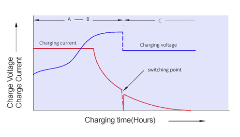
Multi-stage chargers provide microprocessor controlled sensing so charging can be quick and safe. Some of these will start with a bulk constant current value until a predetermine voltage is achieved and then switch to a constant voltage charge where the batteries counter EMF suppresses the current in increasing amounts until the current is at its lowest final charge level. At this final point the charger switches to a float or maintenance charge that is low enough to only compensate for self-discharge and internal resistance.
The charge current limitations are listed on individual specification sheets as they are different for every battery. Generally speaking a C/5 (C = rated Ah) charge level is safe to use on SLA battery types when charging with a standard constant voltage taper current charger.
When a microprocessor multistage charger is used, The initial constant current stage can be as high as C/3 as the charger only allow this constant current stage to remain as long as the voltage levels mentioned above for cycling are not exceeded. The second stage is a taper current stage where the current is allowed to gradually drop and the voltage is held constant. The last stage is a float or maintenance charge mode where the current is reduced to battery acceptance range while and the constant voltage is reduced to the above float voltage ranges. See chart below:
Discharging changes the chemical composition of the battery plates as noted in the chemical formula above and is also critical to the battery life.
The depth of the discharge and the number of discharges the battery is designed to provide must be considered to optimize battery life. All SLA batteries must be fully charged after every discharge to ensure sulfation does not occur before the next discharge event. Long discharge events (20 hours) should be stopped when battery load voltage reaches 1.75 volts per cell (VPC). The battery can be discharged to lower voltages (ex. 1.67VPC) if the discharge time is very short (15 minutes). Discharging the battery below recommended end point voltages should be avoided as damaged to the plates can occur and the battery will not recover to a fully capacity charge status. A cycle is one charge and one discharge event. Depths of discharge cycles are expressed in percentages of rated capacity. A 100% depth of discharge (DOD) represents all the capacity designed into the battery. Batteries can be optimized to cycle more often to differing depths of discharge. Note that a 20% DOD increases the number of available discharge cycles exponentially more than a deeper discharge of 80% DOD. Therefore, planning for shallower discharge cycles should be considered by increasing the battery size (Ah capacity) when possible to optimize cycle life. The chart below shows the varies discharge values at different discharge levels (i.e. 3C current = 3 times rated Ah capacity)
Discharge times for various Discharge values
Temperature affects every aspect of the battery and its life. Both charging and discharging are affected since heat accelerates the chemical reaction and cold slows it down. Therefore, heat increases the rated capacity, but also accelerates the internal degrading progression and shortens the life. Cold reduces the amount of capacity available, but can extend shelf life without boosting.
In a standby or float application for every 15° F incremental temperature increase above 77° life shortens by 50% of design life of the SLA battery. For example if the design life is 5 years in a float application, the battery will only last 2.5 years if maintained at 92°F and will only last 1.25 years at 107°F. Temperature equally affects battery capacity and life in cycling and other applications. However, in cycling applications life is equally affected by the number and depth of cycles in addition to temperature.
Temperature’s Effect on Capacity
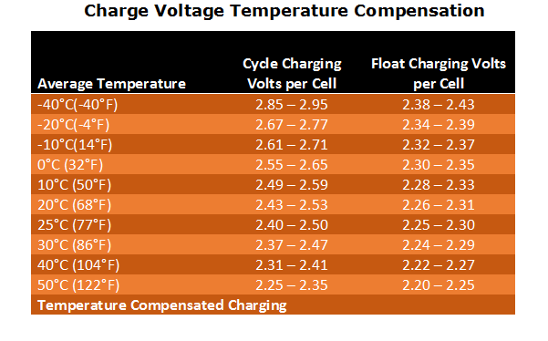
Temperature also affects charging. In higher heat environments the charge voltage should be decreased and when charging in cooler temperatures the charge voltage must be increased. Otherwise charge times must be changed to compensate for the temperature variances. For large drops in temperatures the planned charge times may not be sufficient to fully recharge the battery unless the voltage is temperature compensated. See charge voltage C° temperature compensation values in the graph below:
Overcharging creates additional heat since the battery is not able to absorb the over-capacity in volts and amps being supplied. Since high heat accelerates the chemical reaction the overcharge process will continue to increase heat and the battery will may eventually go into thermal runaway where the higher heat accelerates exponentially until permanent battery damage will result.
The battery self-discharge is also greatly affected by temperature. The battery capacity retention (shelf-life) is dramatically less if the battery is stored at 85°F than if it is stored at 65°F. Batteries stored at 85°F must be boosted more often to ensure capacity retention is maintained. Oracle Battery manufacturing processes are optimized to reduce self-discharge. SLA batteries should be boosted when the remaining capacity drops to 75-80% of rated capacity to ensure no reduction of battery life occurs. The below chart shows some recharge intervals based on average storage temperatures.
Temperature Storage loss:
Average Storage Temperature
|
|
|
|
|
|
|
|
|
|
|
Oracle SLA batteries may be connected in parallel (positive to positive and negative to negative terminals) to increase rated Ah capacity or series connection (positive to negative to positive to negative terminals) to increase voltage of the battery string. The final connection to the application of a battery string should be connected to opposite corners of the string to ensure good current flow from the complete string helping to reduce battery voltage variances over time. All batteries must be matched as closely as possible in age and capacity. Also ensure all terminals are equally torqued and cleaned so variations in connection resistance is reduced.
SLA batteries are generally considered maintenance free since they are valve regulated to outside influence. However, securing terminal connections and checking the battery exterior is required so good current flow in and out of the battery is achieved. This is especially important for strings of batteries connected in series or parallel connections. Some migration of current has been measured on the cover of a battery where grease or other contaminates are allowed to accumulate between the battery terminals resulting in additional discharge of the battery. There are small vent holes on the cover and tops of the batteries that must be kept clean so the pressure relief valves can vent properly.